How to Select a Gear Reducer for Conveyor Systems
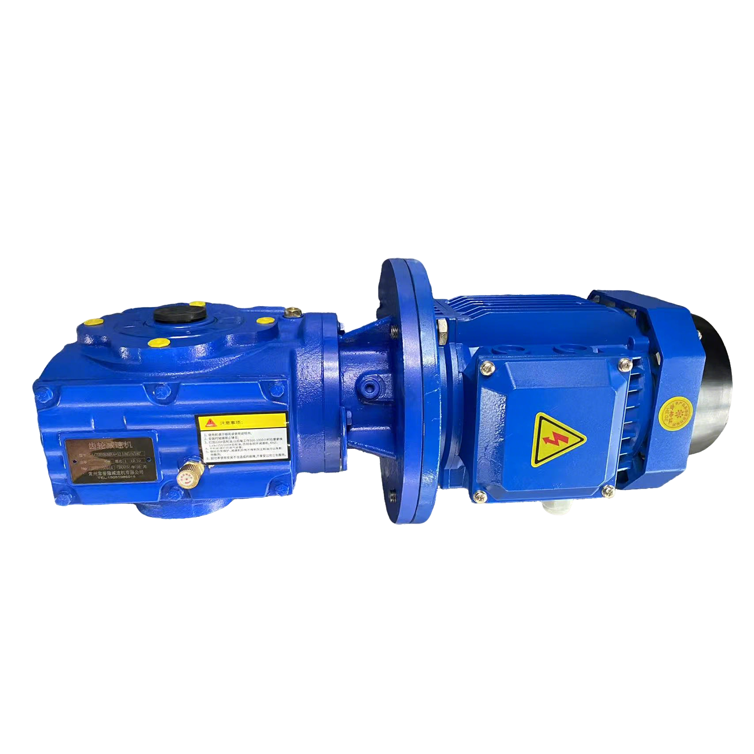
A conveyor gearbox is sized from four numbers: belt speed, drive pulley diameter, effective pull, and duty cycle. Convert those into output speed and output torque, multiply the torque by a service factor of 1.3–1.8, then pick the series by layout — K for right-angle heavy bulk, R for inline, F for narrow frames, S for compact self-locking drives. Get those four numbers right and the frame size follows.
Most conveyor drives fail early for a boring reason: the gearbox was chosen from a catalog page by motor kW instead of by torque at the head shaft. A 15 kW unit and a 15 kW unit can differ by a factor of three in output torque, and the belt only cares about torque at the pulley.
This guide turns a conveyor duty into a gearbox specification in six steps. Every number below comes from the same method our engineers use when quoting OEM conveyor drives for mining, ports, grain terminals, and logistics lines in more than 50 countries.
Key Takeaways
Size from torque at the head shaft, never from motor kW alone.
Output speed comes from belt speed and pulley diameter — not from the gearbox.
Apply a service factor of 1.3–1.8; add 0.25 for 24/7 duty and 0.25–0.5 for frequent starts.
K series handles right-angle, high-torque bulk conveying up to 50,000 Nm; R series covers inline drives up to 18,000 Nm; F series fits narrow frames; S series adds self-locking for inclined and hold-and-release stations.
Always check overhung load at the pulley and thermal capacity — these two reject more selections than torque does.
Mounting position sets the oil level. Wrong position is the most common cause of early seal and bearing failure on conveyor drives.
Step 1 — Collect the Four Numbers
Walk to the conveyor drawing and take these values. Nothing else is needed to start.
| Input | Symbol | Where to Find It | Typical Unit |
|---|---|---|---|
| Belt speed | v | Process sheet, or measure | m/s |
| Drive pulley diameter | D | General arrangement drawing | mm |
| Effective pull (belt tension difference) | F | Calculated from capacity, lift, friction | N or kN |
| Duty cycle | — | Hours/day, starts per hour, reversing? | — |
If the effective pull is not on the drawing, take the absorbed power at the pulley and work backward. On a horizontal belt, effective pull is roughly the sum of friction, incline load, and skirt/plough drag; on an inclined belt, the lift component usually dominates. For a first pass:
P = absorbed power at the pulley in kW | v = belt speed in m/s
Step 2 — Convert to Output Speed and Torque
Two formulas do all the work.
v in m/s, D in metres, n₂ in rpm
F in N, D in metres, T₂ in Nm
Then the ratio follows from motor speed:
n₁ = full-load motor speed (1,450 rpm for a 4-pole 50 Hz motor, 1,750 rpm for 60 Hz).
Worked Example — 200 t/h Bulk Conveyor
| Parameter | Value |
|---|---|
| Belt speed v | 1.6 m/s |
| Drive pulley D | 500 mm (0.5 m) |
| Effective pull F | 12,000 N |
| Output speed n₂ | 60 × 1.6 / (π × 0.5) = 61 rpm |
| Output torque T₂ | 12,000 × 0.25 = 3,000 Nm |
| Motor | 4-pole, 1,450 rpm |
| Ratio i | 1,450 / 61 = 23.7 : 1 |
| Absorbed power at pulley | 3,000 × 61 / 9,550 = 19.2 kW |
| Motor selected (95% gearbox efficiency) | 22 kW |
Step 3 — Apply the Service Factor
Rated torque alone under-sizes the unit. The service factor (SF) converts your running torque into the rating you must specify:
| Duty Condition | Service Factor |
|---|---|
| Uniform load, 8–10 h/day | 1.0 – 1.25 |
| Moderate shock, 8–10 h/day | 1.25 – 1.5 |
| Heavy shock (lump feed, reversing, jam-prone), 8–10 h/day | 1.5 – 1.75 |
| Continuous 24 h duty | add 0.25 |
| Frequent starts (10+/hour) | add 0.25 – 0.5 |
| Reversing duty | add 0.5, or specify a reversing-duty unit |
Conveyors that start fully loaded, incline conveyors with material surge, and any belt fed by a hopper without a control gate belong in the heavy-shock column. In the example above, 3,000 Nm at SF 1.5 becomes 4,500 Nm, and a nominal 4,300 Nm frame is no longer acceptable.
Continuous torque sizes the thermal rating, while peak torque (start-up, jam, plugging) sizes the mechanical rating. Belt conveyors regularly demand 180–250% of running torque for a few seconds at start.
Step 4 — Choose the Series by Layout and Load
Once torque and ratio are fixed, series selection becomes geometry.
| Series | Layout | Max Output Torque | Ratio Range | Best Conveyor Fit |
|---|---|---|---|---|
| K helical-bevel | Right angle, output shaft 90° to input | 50,000 Nm | 3.98 – 197.37 | Heavy bulk: mining, port, cement, inclined long belts, head drives needing a right angle |
| R inline helical | Coaxial, inline | 18,000 Nm | Single-stage to combined (hundreds) | Straight-run conveyors, belt and roller lines where the motor sits behind the pulley |
| F parallel shaft | Parallel offset shafts | 18,000 Nm | Two- and three-stage | Narrow frames, low headroom, side-mounted drives |
| S helical-worm | Right angle, helical + worm | 4,000 Nm | High ratios in one compact case | Light conveying, packaging, hold-and-release, inclined units needing self-locking |
| NMRV / WP worm | Right angle, worm only | Light duty | High ratios | Small logistics and food-handling belts under a few hundred Nm |
| Cycloidal (B/X, BLD/XWD) | Inline, pin-wheel | High shock capacity | Single stage to 1:87 | Shock-loaded starts, harsh duty where impact resistance beats efficiency |
Quick Rules That Decide Most Conveyor Jobs
Right angle + heavy shock → K series. This is the standard for bulk material handling.
Inline + continuous high speed → R series. Above 95% efficiency matters on 24/7 lines.
Frame too narrow for a right-angle housing → F series. The slim parallel-shaft body is the reason this series exists.
Inclined belt that must hold position when stopped → S series. The worm stage gives self-locking without a brake.
Frequent jam-and-restart, dirty environment → cycloidal. The pin-wheel design absorbs shock that wears helical teeth.
Across the R/S/K/F line, every unit uses 20CrMnTi alloy steel case hardened to 58–62 HRC and CNC-ground to DIN 6 accuracy, so the series choice is about layout and load — not about a quality tier. Review the full R/S/K/F series matrix before you commit to a frame.
Need Help Selecting the Right Conveyor Gear Reducer?
Share your conveyor speed, torque, pulley diameter, and installation requirements. Our engineering team can help identify the suitable gearbox series and configuration.
Send Your Conveyor RequirementsStep 5 — Match the Mounting to the Head Shaft
Conveyor drives are usually specified by how they attach, not by how they look.
| Mounting | When to Use | Watch Out For |
|---|---|---|
| Foot mounted, solid shaft | Conventional head shaft with a coupling | Alignment and shim packs; foundation stiffness |
| Flange mounted (B5 / B14) | Motor or gearbox bolted to a machined face | Flange bolt grade and face flatness |
| Hollow shaft with keyway | Direct-mounted on the head shaft, no coupling | Shaft fit tolerance, puller access for removal |
| Hollow shaft + shrink disc | High torque, no keyway wear, frequent reversals | Correct disc torque; clean, dry shaft |
| Hollow shaft + torque arm | Shaft-mounted drives on conveyors and screw conveyors | Torque arm anchor must take full reaction torque |
For shaft-mounted conveyor drives, the torque-arm versions are the workhorses: KAT torque-arm helical-bevel for heavy bulk, FAT torque-arm parallel shaft for narrow frames, SAT torque-arm helical-worm for light duty. They remove the coupling, cut the installed length, and eliminate a whole class of misalignment failures.
Step 6 — Check the Two Limits That Reject Selections
Torque and ratio get you a candidate. These two checks decide whether it survives.
1. Overhung Load (Radial Load) at the Pulley
A V-belt or chain drive on the gearbox output puts a bending load on the shaft that has nothing to do with torque. Calculate it, compare it with the published allowable at the mid-point of the shaft extension, and derate for the actual load position. If you exceed it, move to belt-and-pulley geometry, a larger frame, or a separate bearing block. This is the single most common cause of broken output shafts on conveyor drives.
2. Thermal Capacity
Continuous-duty conveyors run hot. Check the thermal rating at your ambient temperature and mounting position, not just the mechanical rating. Above roughly 40 °C ambient, or in an enclosure without airflow, ask for the thermal rating curve — and consider a fan-cooled or larger frame.
Then confirm the boring things: IP rating against washdown and dust, oil level for your mounting position (M1–M6), breather and drain access, and the motor flange standard (IEC or NEMA) that your market uses.
Common Selection Mistakes on Conveyor Drives
Sizing on motor kW. Two 15 kW units can differ 3× in output torque. Always size on torque at the head shaft.
Ignoring start-up torque. A fully loaded belt can pull 200%+ of running torque for seconds. Shock capacity is a mechanical rating, not a thermal one.
Wrong mounting position. Mounting position sets the oil level. Fill to the wrong mark and the first bearing starves within weeks.
No service factor for lump feed. Belt ploughs, skirtboards, and uncontrolled hopper feed create impact the average torque never shows.
Skipping the overhung load check when a pulley or sprocket sits on the output shaft.
Mixing flange standards. An IEC B5 motor will not bolt to a NEMA face — confirm at quote stage, because retrofitting a flange is a machining job.
Send These Six Items for a Same-Day Selection
Belt speed, pulley diameter, and effective pull (or absorbed power).
Duty cycle: hours/day, starts per hour, reversing or not.
Mounting: foot, flange, hollow shaft, torque arm; and mounting position.
Available space, especially distance from pulley centre to nearest obstruction.
Site conditions: dust, washdown, ambient temperature, altitude.
Motor supply: voltage, frequency, IEC or NEMA frame.
Engineering Support for Conveyor OEM Projects
Our engineering team returns a frame selection, ratio, and 3D CAD model within 48 hours, and custom output shafts, flanges, and ratios are machined in-house — which is how a conveyor OEM gets a drop-in replacement instead of an adapter plate. Send your conveyor duty to an engineer and get the frame confirmed before you cut steel.
Get a Gearbox Recommendation for Your Conveyor Project
Send us your operating parameters, mounting dimensions, motor specifications, and site conditions. Get engineering assistance with gearbox sizing, ratio selection, and customized configurations.
Request a Technical QuotationFrequently Asked Questions
1. What size gearbox do I need for a belt conveyor?
Divide motor speed by the output speed you calculated from belt speed and pulley diameter to get the ratio. Multiply the head-shaft torque by a service factor of 1.3–1.8 to get the required rating. Example: 3,000 Nm running torque × 1.5 = 4,500 Nm required, at roughly 24:1 from a 4-pole motor.
2. Should I use a K series or an R series gearbox for a conveyor?
Use K when you need a right angle to the belt or you are moving heavy bulk with shock loads — it reaches 50,000 Nm. Use R when the motor can sit inline behind the pulley and you want the highest efficiency above 95%. Use F when the frame is too narrow for a right-angle housing.
3. What service factor should a conveyor gearbox have?
Start at 1.25 for uniform loads, 1.5 for moderate shock, and 1.75 for heavy shock such as lump feed or jam-prone belts. Add 0.25 for 24-hour duty and 0.25–0.5 when the conveyor starts more than ten times an hour. Reversing duty needs another 0.5.
4. Can a gearbox be mounted directly on the conveyor head shaft?
Yes. Hollow-shaft versions mount straight onto the head shaft and need no coupling. For high torque or frequent reversing, specify a shrink-disc version to avoid keyway wear; for shaft-mounted drives, add a torque arm so the reaction torque has a defined anchor point.
5. Why did my conveyor gearbox fail at the output shaft?
Almost always overhung load. A pulley or sprocket on the output shaft bends it in a way torque ratings never describe. Check the allowable radial load at your actual load position, and add a bearing block or a larger frame if you exceed it.
6. How long does a conveyor gearbox take to ship?
Standard configurations ship in 7–15 days from our China facility, and every unit is load, noise, and oil-leak tested before packing. Non-standard shafts and flanges add machining time, confirmed at quote stage.
Looking for a Reliable Gear Reducer for Your Conveyor System?
Whether you need an inline helical, helical-bevel, parallel-shaft, or shaft-mounted gearbox, share your conveyor operating conditions with our engineering team.
Contact Our Gearbox Engineers