

Helical Gearbox vs Worm Gearbox: Which One Is Better for Industrial Applications?
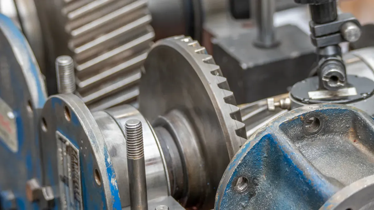
When selecting the ideal power transmission solution for industrial machinery, evaluating the key differences between a helical gearbox vs worm gearbox is essential for maximizing operational efficiency. Helical gearboxes excel in heavy-duty continuous applications, delivering over 95% mechanical efficiency and robust power output. On the other hand, a helical gearbox vs worm gearbox comparison highlights that worm units fit remarkably well into compact spaces, offering substantial single-stage speed reductions alongside inherent self-locking capabilities for added safety.
Changzhou Changyulong Reducer Co., Ltd. produces premier industrial gearboxes compliant with strict ISO 9001:2015 and CE standards. Utilizing advanced CNC gear grinding to achieve DIN 6 precision accuracy, Changyulong provides exceptional power transmission across both design categories.
When conducting a helical gearbox vs worm gearbox analysis for demanding applications, engineers must carefully evaluate mechanical efficiency, output torque density, thermal dissipation limits, and spatial constraints alongside the total cost of ownership. By partnering with Changzhou Changyulong Reducer Co., Ltd., you can select the perfect drive system engineered to optimize your specific manufacturing performance today.
Key Takeaways
Helical gearboxes save energy. They are over 95% efficient. This makes them great for heavy continuous work.
Worm gearboxes fit small areas well. They give great speed reduction quickly. They work in one tiny unit.
Worm gearboxes stop backward motion naturally. They offer extra safety. This helps lifting systems when power fails.
Helical gearboxes cost more at first. But they use less energy. This saves money over time.
Mechanical Principles of Helical Gearboxes and Worm Gearboxes
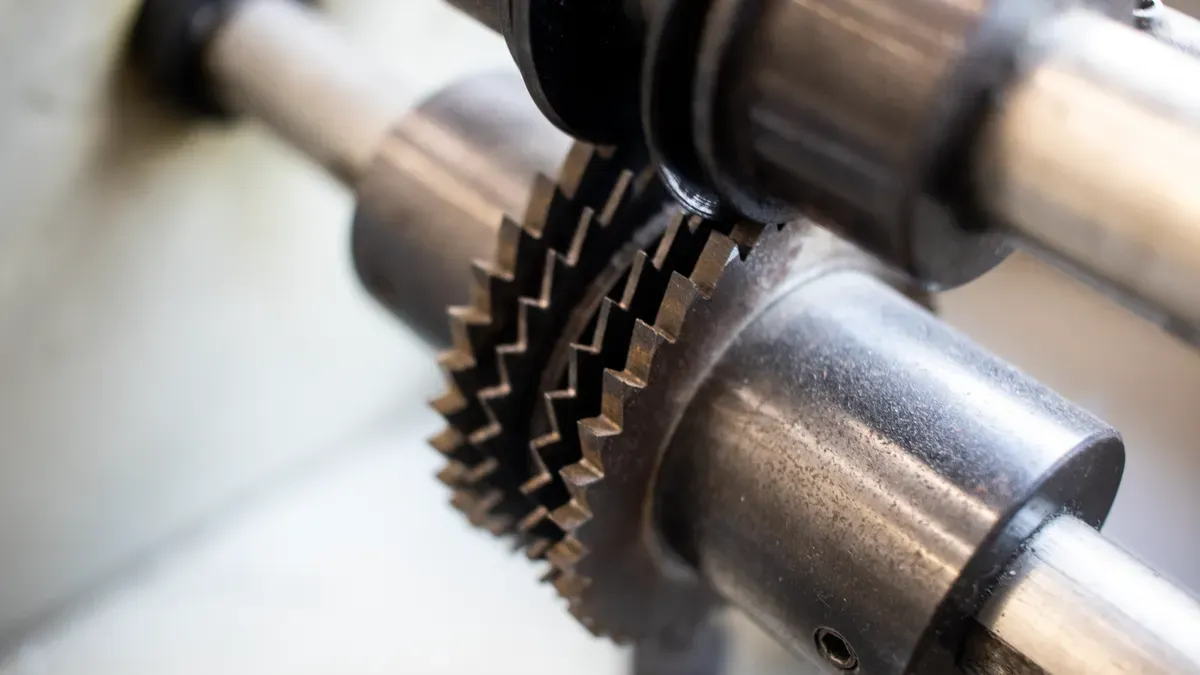
Engineers pick drives based on gear shape. They check how gear teeth transfer power. This helps choose the right factory unit.
Helical Gear Design and Rolling Contact Kinematics
Helical gearboxes feature angled teeth. These teeth sit on a round gear face. They touch slowly along a diagonal line. You get rolling contact during operation. This stops direct hard impacts. The design creates continuous tooth contact. It spreads heavy loads evenly across gears. Your machines gain high shock load strength. They run much smoother under heavy duty.
Parameter | Helical Gears | Worm Gears |
|---|---|---|
Primary Contact Type | Slow rolling and sliding contact | Mostly sliding across all teeth |
Kinematic Behavior | Gears roll together to cut friction | Teeth slide constantly during operation |
Thermal & Friction Output | Low heat and very low friction | High friction makes a lot heat |
Mechanical Efficiency | High efficiency from 90% to 99%+ | Low efficiency from 30% to 90% |
Careful building helps these moving parts work better. Changzhou Changyulong Reducer Co., Ltd. uses strong gear grinders. They reach DIN 6 accuracy on many gearboxes. These include the R, S, K, F series. Exact gear teeth lower internal friction losses. You get over 95% gear efficiency. Machines make less noise during long runs. Gear drives last much longer over time.
Worm Gear Architecture and Sliding Contact Mechanics
Worm gearboxes use a crossed layout. A threaded screw connects to a wheel. The input screw turns against bronze teeth. These surfaces slide continuously against each other. High friction lowers speed drive efficiency. It works worse than helical units.
The screw angle changes power conversion efficiency. Steeper angles up to 20° boost efficiency. They increase forward motion for better speed. Shallow angles below 5° cut efficiency. They drop performance below 50% from high friction. You can pick NMRV, WP, SWL series. Changyulong offers these low cost speed reducers.
Efficiency, Torque, and Thermal Performance
Mechanical Efficiency and Power Dissipation
Power choices change your costs over time. Gear designs control energy use and power loss.
Gearbox Type | Operational Efficiency Rate | Thermal Dissipation & Operational Limit |
|---|---|---|
Keeps 94%–98% energy (96%–98% at 10:1, 95%–97% at 50:1, and 94%–96% at 100:1) | Sheds heat quickly with low friction. Works nonstop 24/7 easily. | |
Worm Gearbox | Drops from 85%–90% at 10:1 down to 50%–60% at 100:1 | Traps heat inside the metal box. Needs cooling breaks or extra fans. |
Rolling teeth save energy in all steps. Higher efficiency cuts daily power bills. You get more power with less wasted energy.
Output Torque Capacity and Shock Load Resistance
Big factory work needs strong turning force. A helical unit handles heavy strain better. Slanted teeth share forces across many points. This shape gives more force and resists shocks.
Worm units fit lower force needs. Hard shocks ruin sliding worm parts quickly. Helical units stay strong during sudden hits. Your machines stay safe under big stress.
Heat Generation and Duty Cycle Constraints
Friction changes heat levels in long jobs. Sliding worm parts make heat very fast. High heat forces stops to protect oil.
Helical drives cool well with rolling movements. Low gear efficiency wastes energy in worms. High gear efficiency keeps performance very stable. Helical drives run continuously without heat danger.
Spatial Footprint and Reduction Ratio Capabilities
Space and speed limits control drive choices. You balance size and output power for machines.
Multi-Stage Inline and Bevel Helical Arrangements
Check your floor space when building machines. Helical gearboxes offer great power. One gear set cannot reach 60:1 ratios. You stack gear pairs in stages instead. This multi-stage setup lowers speed for heavy work.
These inline and bevel setups use extra room. Bigger frames give more torque density for tasks. Extra gear sets add length and weight. You need extra mounting space for these drives.
High Single-Stage Ratios in Compact Worm Units
A worm gearbox fits small spaces easily. The 90-degree right-angle layout saves floor room. One worm gearbox set gives 5:1 to 100:1 ratios. A single screw turns an 80-tooth wheel. This makes an 80:1 speed reduction fast. You do not need extra gear parts.
This smart design keeps the drive small. Yet, an 80:1 ratio drops mechanical efficiency. Efficiency falls between 45% and 55%. Most setups stay near 70:1 ratios. This stops bad friction heat during long runs.
Feature / Criterion | Worm Gear Units | Helical Gear Units |
|---|---|---|
Single-Stage Reduction Capability | Reaches high ratios above 60:1 (up to 100:1) | Unable to achieve ratios above 60:1 |
Design Complexity for High Ratios | Maintains compact 90-degree geometry | Requires multi-stage gear pairs |
Footprint Efficiency | Highly space-efficient in smaller frames | Larger footprint due to multi-stage expansion |
Self-Locking Dynamics and Backdriving Safety
Study how drives hold loads safely during power outages. Tooth shapes create unique holding power for heavy machines.
Static Self-Locking Mechanics in Worm Drives
A worm gearbox offers special self-locking advantages. Locking happens when lead angles stay below friction angles. Steel and bronze gear pairs use 6° to 8.5° friction angles. Precise design choices set exact safety levels.
Design Requirement | Lead Angle Threshold |
|---|---|
Basic Mathematical Condition | Lead angle less than or equal to friction angle |
Guaranteed Self-Locking Target | Lead angle under 5° |
High Reliability Threshold | Lead angle under 3.5° |
Critical Lifting Applications | Lead angle less than or equal to 3° |
Shaking can break static friction. Mechanical conditions reveal common operational failure paths:
Transition to Dynamic Friction: Shaking causes movement. Friction drops below the lead angle.
Increased Sliding Velocity: Mesh motion speeds sliding. Faster motion lowers friction fast.
Rotor and Assembly Imbalance: Unbalanced motor parts spin. Extra force overcomes weak friction.
External Braking Requirements for Helical Units
A helical gearbox cannot hold loads safely. High mechanical efficiency lets gears turn backward easily. Internal friction fails to stop reverse movement during outages.
Slanted lifts drop fast without extra safety brakes. You must attach an external motor brake immediately. Fail-safe brakes stop loads during sudden power cuts. External brakes keep continuous lifting tasks completely safe.
Helical Gearbox vs Worm Gearbox: Total Cost of Ownership
Smart money choices need clear planning. You must check upfront costs. You also check lifelong running costs. Comparing a helical gearbox vs worm gearbox shows clear perks. These depend on your cash plan. They also depend on plant work.
Initial Capital Expenditure Comparison
Worm gearboxes cost less money upfront. Budget managers like these low prices. Simple design layouts make worm drives cheap. They are fast to build. They are easy to buy. Small factories pick worm units often. They save money on light machinery.
Low starting costs do not save money later. High-efficiency helical gearboxes cost more money first. They use gear teeth ground with care. Helical gearboxes run all the time. They save lots of power. These power savings pay back the price.
Expense Category | Worm Drives | Helical Drives |
|---|---|---|
Initial Capital Outlay | Lower upfront cost | Higher initial investment |
Energy Consumption | Higher energy loss | Lower long-term power usage |
Primary Wear Component | Bronze worm wheel | Heavy-duty thrust bearings |
Long-Term Energy Costs and Wear Maintenance
Running costs depend on power use. They also depend on gear wear. Sliding parts inside worm gearboxes rub. This causes continuous friction loss. This friction wastes electricity every day. It lowers energy efficiency during work.
Operating Efficiency Loss = Energy Wasted as Heat
Helical designs get top efficiency scores. Smooth rolling parts reach over 95% efficiency. Less power loss cuts electric bills fast. Hardened steel gear teeth last longer. Their surfaces stay strong over time.
Maintenance Factor | Worm Drives | Helical Drives |
|---|---|---|
Friction Type | Sliding friction | Rolling contact friction |
Maintenance Need | Soft bronze wheel replacement | Periodic thrust bearing checks |
Operational Lifetime | Frequent component replacement | Extended uninterrupted operation |
Changzhou Changyulong Reducer Co., Ltd. helps buyers globally. Direct factory builds cut middleman prices. Costs drop across all product series. Engineers make custom flanges and shafts. They send free 3D CAD models fast. You get them within 48 hours. Fast models speed up machine design. They also lower total machine setup costs.
Selecting the Right Gearbox for Industrial Applications
Smart gear choice runs plants well. Pick clear performance goals first. Good gear choices cut costs.
Helical Applications: Continuous Heavy-Duty Machinery
Continuous jobs need steady power. Use helical gearboxes for non-stop work. Strong machines use these drives:
Steel lines shaping metal slabs
Long belts moving bulk goods
Large mixers blending thick fluids
Plastic extruders using ZLYJ units
High efficiency cuts power costs. Angled teeth mesh very smoothly. This lowers shakes and stress. Units keep efficiency past 95%. Gears last long with easy care.
Worm Applications: Intermittent Motion and Hoisting Systems
Small machines need compact drives. A worm gearbox fits small budgets. Small drives turn conveyor belts. They turn valves and lifts.
Worm drives suit short jobs. Right-angle screws hold loads well. Self-locking traits make lifts safe:
Holds loads without using brakes
Cuts brake wear during use
Keeps loads safe during outages
Softens shocks while lifting goods
How to Choose the Right Gearbox
Buyers check key technical points. Review duty cycles and heat. Check drive size and power.
Criteria Category | Evaluation Parameter | Key Considerations for Procurement |
|---|---|---|
Duty Cycle | Fleet usage & shift patterns | Check run hours like 2,000. Clarify long shift plans. |
Ambient Temperature | Thermal derating & lab conditions | Ask for heat rating limits. Check test oil heat. |
Overhung Loads | Driveline geometry & stress | Check setup shapes for stress. Extra load wears bearings. |
Find thermal power with this math:
P_th = P_th,20°C x f_t x stream x f_h x f_m
This math uses heat factor (f_t) and cycle factor (f_m). Keep input speeds below set limits. Keep power under thermal limits. For short jobs, use mean torque. Matching gear choices protects your equipment.
markdown
Comparing a helical gearbox vs worm gearbox helps you choose right drives. Helical designs save energy during heavy work. Worm units offer smaller shapes for tight spaces. They also lock themselves safely.
Changzhou Changyulong Reducer Co., Ltd. makes strong gearboxes. They follow strict ISO 9001:2015 rules. They also meet CE standards. Good building methods keep gears working long. Each product runs very reliably.
Talk with our technical team today. Ask for custom flange 3D CAD models. Get shaft models within 48 hours. Speed up your machine designs right now.
markdown
FAQ
What is the main efficiency difference in a helical gearbox vs worm gearbox evaluation?
Helical gearboxes roll teeth together. This saves energy fast. Efficiency tops 95% easily. Worm gearboxes slide teeth instead. Sliding creates extra friction heat. Wasted energy drops output power.
When should you choose a worm gearbox for your application?
Pick worm gearboxes for tight spaces. Right-angle designs cut speed fast. Single stages handle big reductions. They lock safely in place. Use them on small conveyors. They move valves and lifts well.
Why do helical gearboxes perform better in continuous heavy-duty operations?
Helical gearboxes use angled teeth. Teeth spread heavy loads evenly. Loads cross many contact points. Internal friction drops down fast. Drives handle big shock hits. They run cool non-stop daily.
How fast can Changzhou Changyulong Reducer Co., Ltd. provide custom CAD models?
Changzhou Changyulong Reducer Co., Ltd. helps fast. Get custom 3D CAD models quickly. Engineers build flanges and shafts. Models arrive within 48 hours. Add files directly to designs.